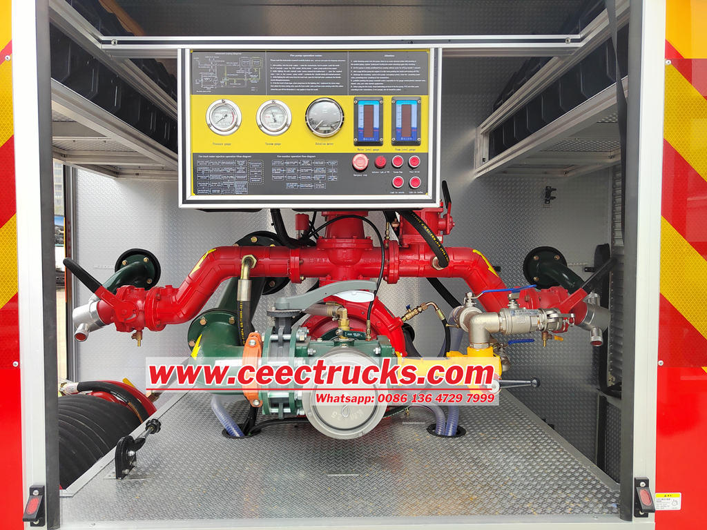
The CB series of vehicle-mounted fire pumps, based on the advantages of fire pumps from Germany, Austria, and the United States, has undergone comprehensive optimization and innovation, resulting in the introduction of new models: CB10/30, CB10/40, CB10/60, and CB10/80 low-pressure vehicle-mounted fire pumps.
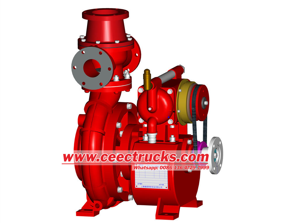
The CB series of low-pressure vehicle fire pumps are characterized by excellent performance, high efficiency, compact structure, aesthetically pleasing design, simple operation, and convenient maintenance. Additionally, the pump casing adopts a guide vane design, and the impeller incorporates a balanced ring and balanced hole structure, significantly reducing axial and radial forces, thereby enhancing durability. All performance metrics comply with the GB6245-2006 standard and have successfully passed the type testing conducted by the National Fire Equipment Quality Supervision and Inspection Center.
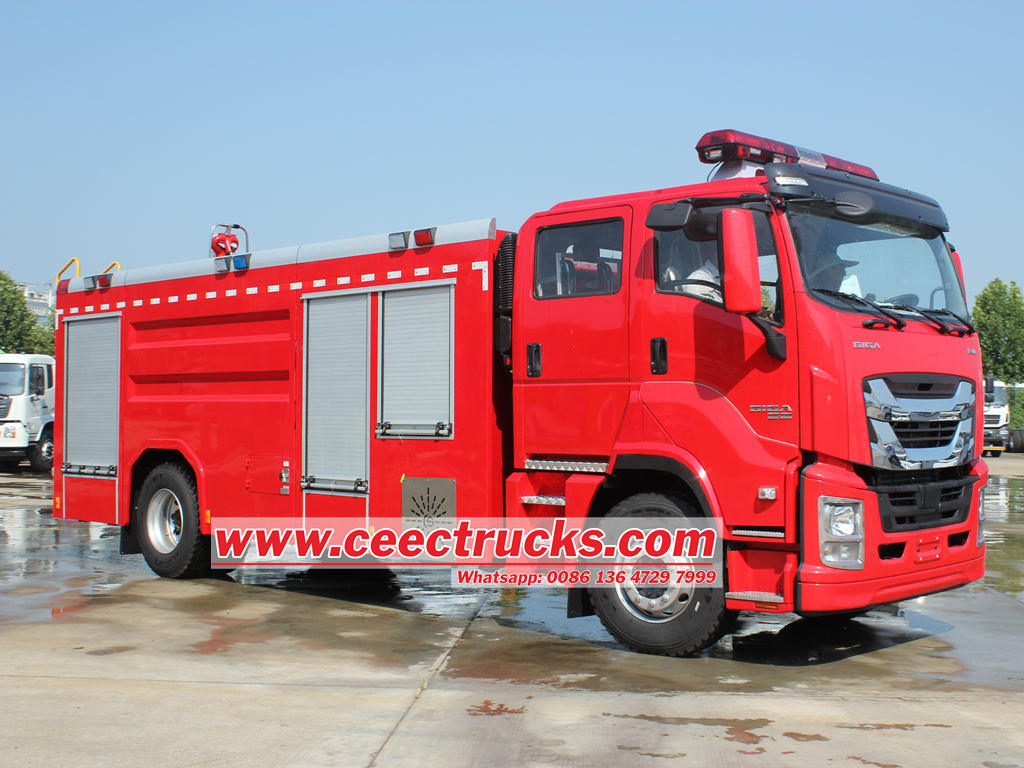
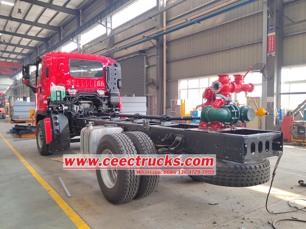
As an upgraded product of the current domestic fire pumps in China, this low-pressure series of vehicle-mounted fire pumps has not only emerged in the domestic market but also boasts performance and quality comparable to similar foreign products. It is an ideal choice for fire truck modification factories, suitable for modifying various types of vehicles such as light, medium, and heavy water tenders, foam fire trucks, and high-pressure spray fire trucks. Simultaneously, it can also be utilized in fixed pump sets, meeting a broader range of firefighting needs.
1. Maximum vacuum rate for fire pump:
Chart 1
|
Model |
Inlet (mm) |
Outlet(mm) |
Maximum vacuum(KPa) |
Vacuum rate within 1 min(KPa) |
7m suction time(S) |
|
|
Low pressure |
Medium pressure |
|||||
|
CB10/20-XZ |
φ100 |
φ65 |
|
≥85 |
<2.6 |
25 |
|
CB10/30-XZ |
φ100 |
φ80 |
|
≥85 |
<2.6 |
25 |
|
CB10/40-XZ |
φ125 |
φ80 |
|
≥85 |
<2.6 |
25 |
|
CB10/60-XZ |
φ150 |
φ100 |
|
≥85 |
<2.6 |
43.6 |
|
CB10/80-XZ |
φ150 |
φ100 |
|
≥85 |
<2.6 |
45 |
2. Main parameter for fire pump
Chart 2
|
Name |
Model |
Work Condition |
Flow rate (L/S) |
Outlet pressure (Mpa) |
Rated speed (r/min) |
Power (KW) |
Suction depth (m) |
|
Low pressure fire pump |
CB10/20-XZ |
1 |
20 |
1 |
3070±50 |
34.29 |
3 |
|
2 |
14 |
1.3 |
3380±50 |
35.36 |
3 |
||
|
3 |
10 |
1 |
3115±50 |
27.42 |
7 |
||
|
Low pressure fire pump |
CB10/30-XZ |
1 |
30 |
1 |
3010±50 |
50 |
3 |
|
2 |
21 |
1.3 |
3340±50 |
55.2 |
3 |
||
|
3 |
15 |
1 |
3000±50 |
38.6 |
7 |
||
|
Low pressure fire pump |
CB10/40-XZ |
1 |
40 |
1 |
3080±50 |
62.92 |
3 |
|
2 |
28 |
1.3 |
3360±50 |
63.92 |
3 |
||
|
3 |
20 |
1 |
2990±50 |
41.95 |
7 |
||
|
Low pressure fire pump |
CB10/60-XZ(1:1.346) |
1 |
60 |
1 |
3200±50 |
97.72 |
3 |
|
2 |
42 |
1.3 |
3475±50 |
105.76 |
3 |
||
|
3 |
30 |
1 |
3130±50 |
72.75 |
7 |
||
|
Low pressure fire pump |
CB10/80-XZ (1:1.44) |
1 |
80 |
1 |
3400±50 |
137.6 |
3 |
|
2 |
56 |
1.3 |
3500±50 |
127.11 |
3 |
||
|
3 |
40 |
1 |
3130±50 |
83.75 |
7 |
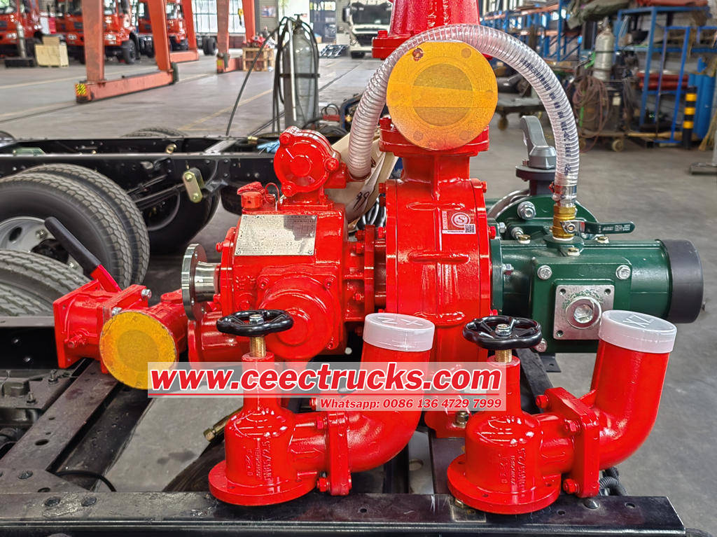
3. Main Structure and Function of Fire Pump
(1) Main Structure
The low-pressure series of vehicle-mounted fire pumps consist of a water pump section, a new piston water primer, a gearbox, an outlet pipe, and an inlet pipe.
(2) Main Components and Their Functions
a. The water pump section is composed of a guide vane pump casing, pump cover, pump shaft, impeller, and mechanical seal.
The new series of low-pressure vehicle-mounted fire pumps adopts spatial guide vanes for flow guidance, balancing the radial force on the pump shaft. The back of the impeller uses a balancing ring with balancing holes, which balances the axial force on the pump shaft and improves the pump's efficiency and service life. The pressure end of the pump shaft adopts a mechanical seal, significantly improving sealing performance.
b. Water Primer Section: The CB10/30, 40, and 60 pumps use a new, oil-free, dual-piston water primer consisting of a piston pump body, eccentric mechanism, piston, intake and exhaust valves, automatic release device, and electromagnetic clutch. It is installed on the gearbox. The piston pump is driven by a belt connected to the pulley on the pump shaft and the pulley on the piston pump. When the water primer is activated, the piston performs a reciprocating motion under the action of the eccentric mechanism, initiating water priming. When the pressure reaches 0.2 MPa, the pressure controller automatically cuts off the power, stopping the operation.
c. The gearbox features a single-stage helical gear transmission. The box is filled with lubricating oil and equipped with a radiator. Pressure water from the pump cools the oil temperature inside the box, improving the gearbox's transmission efficiency and the transmission conditions of gears and bearings. The gear ratio of the gearbox is determined based on the engine speed and power take-off (PTO) ratio.
d. A water priming valve is installed in the water inlet pipe, which must remain open. Otherwise, air cannot be expelled from the pump and inlet pipe, causing priming failure. This valve should only be closed when checking the pump and pipe sealing.
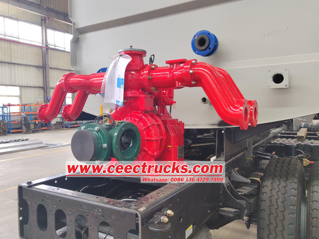
4. Outside drawing for fire pump
Picture 1 Low pressure fire pump outside drawing
Rear Install Model:
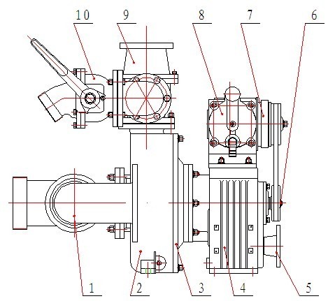
1 Inlet three-way Valve 2 Shell 3 Rear cover 4 Gearbox 5 Shaft coupling flange 6 belt wheel 7 Electromagnetic clutch 8 Piston primer pump 9 Back-pressure valve 10 Outlet ball valve
Middle Install Model:
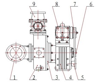
1 Inlet three-way Valve 2 Shell 3 Rear cover 4 Gearbox 5 Shaft coupling flange 6 belt wheel 7 Electromagnetic clutch 8 Piston primer pump 9 Back-pressure valve
